SW1200 Instructions
Questions? Contact me at thezmaker@gmail.com
Tools Needed
Flat Head Screw Driver (5/64 or 3/32)
Phillips Head Screw Driver (#0)
#00-90 Tap and Drill
Needle Nose Pliers
Standard Flat Surface Pliers
Soldering Iron
Primer for metal
Recommended Tools
Handrail Kit with Wires and Resistor
Wire Stripper made to strip 30 AWG wire
Tamiya Surface Primer for Plastic and Metal (works equally well for the shell, frame, fuel tanks and truck parts)
Micro Trains Tap and Drill set for coupler mounting
Metal Files for smoothing out print lines if desired
Running the locomotive
Use 9 volts or less to run the locomotive if installing the resistor. Use a PWM type of throttle for best results. If you don’t install the resistor, use 1.5 to 3 volts max.
Prep the Shorty

Prep the Shorty First
If you have not already done so, follow all steps in the “Shorty Prep” page to prep the motor and trucks. Then return to this page to begin constructing your SW1200.
Click the green button below.
Clean Up and Preparation

3D Printed Brass Models
Brass prints are printed in wax and then cast in metal. All brass parts are put into a tumbler to improve the surface. However, the tumbler's smoothing medium cannot reach some areas of the print. Use metal files before painting to smooth rough surfaces. Another good time to sand down the rough areas is after the first coat of primer.
Check Print Integrity
Due to the metal casting process, even a good print can be slightly out of shape. Inspect the model and verify all major surfaces are straight and flat. Print lines are unavoidable and do not disqualify a good print. The goal here is make sure the model is square and not warped. Some common areas to check are listed below.
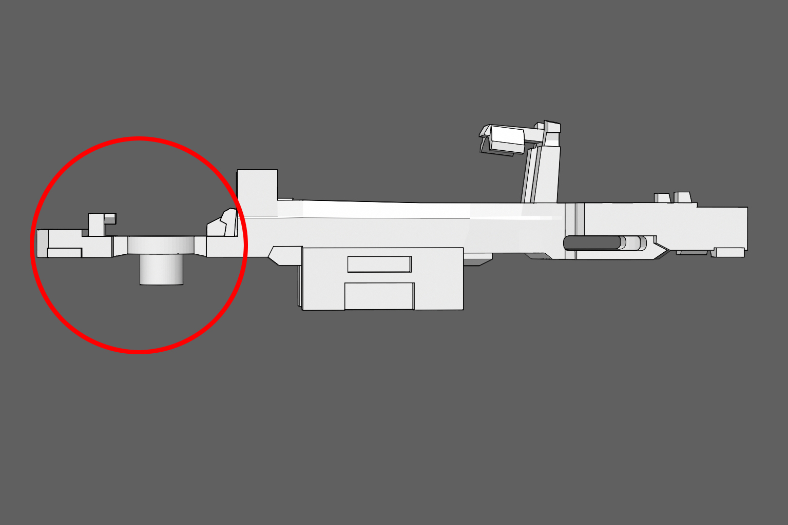
The Frame
The frame has much less mass in the front area (circled in red) compared to the rear. This area can be bent during printing, tumbling, or shipping. Make sure the frame is straight. If it is misshapen, use pliers to straighten it.

Pilot Wall
The wall between the pilot and the stair case can be slightly bent during the smoothing process. It can be put back into shape with needle nose pliers. The etched metal handrails will be glued to the pilot wall so make sure it is square.

Pin Bar
The pin bar holds the pin that mounts the powered truck to the frame. This spot, like the pilot wall, can be bent during the tumbling process. A small screw driver can be wedged into the open space to straighten out the bar, if needed. Go slowly, it can easily be bent too much.

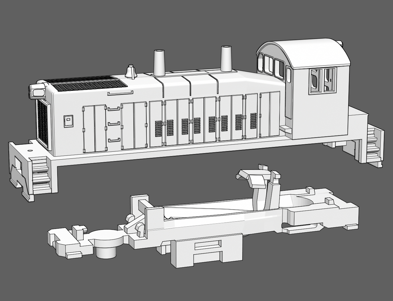
Test Fit
Test the fit of the frame into the shell. The shell may need to be pried open a slight amount to allow the frame to fit into it. Notice the four tabs on the four corners of the frame (circled in red). This is the resting place for the shell. Do not push the shell past the tabs.

Serious Problems?
Shapeways guarantees quality prints. If your print is severly warped or it is damaged, or you simply have questions, contact the help desk; here.
Assemble the Motor and Frame

Clean it first
Clean the brass shell, frame and handrails with rubbing alcohol. Scrub the shell and frame with a tooth brush to remove the anti-tarnish coating applied by the factory. The handrails can be placed in an alcohol bath without scrubbing. Dawn dish detergent works as an alternative to alcohol. Wait for the parts to be completely dry before moving on.

Step 1
Locate the hole under the frame that will hold the Shorty's truck screw. Use a #00-90 tap to thread the hole for the screw.

Step 2
1. Mask the area where the fuel tank will be glued (seen in blue).
2. Apply a coat of primer to the frame. Use primer intended for metal and be sure it is compatible with the paint you will use. For best results, use an air brush or any spray can with a fine mist tip.

Step 3
(After primer has dried and cured)
Use pliers to bend the motor clamp about fifteen degrees upward.

Step 4
Place the motor into the frame. Orient it so the circuit board sits exactly as seen in the illustration.

Step 5
Push the motor downward into the cradle. Leave no space between the motor and the cradle. Pliers can be used to squeeze the motor into place if the fit is too tight..

Step 6
Close the motor clamp with pliers.
Step 7
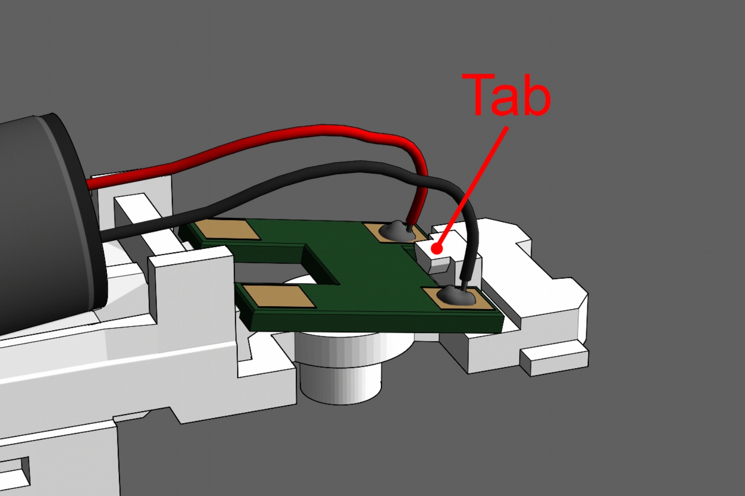
Set the circuit board on the frame and slide it under the tab. Place it with the same orientation as seen in the image.

Step 8
Push the board down past the clamps that sit behind the motor. Pliers can be used to squeeze each side of the board until it sits flat on the frame.
If the sides of the circuit board protrude out the sides of the frame, sand the board so that it is flush with the side of the frame.

Step 9
If the board is not held tight in place, use a screw driver to wedge the clamps shut. Use the cross bar behind the motor as leverage for the screw driver.

Step 10
Cut the black wire and strip it to prepare for installing the resistor.
NOTE: Skip this step and step 11 if you opt not to install the electronic resistor.
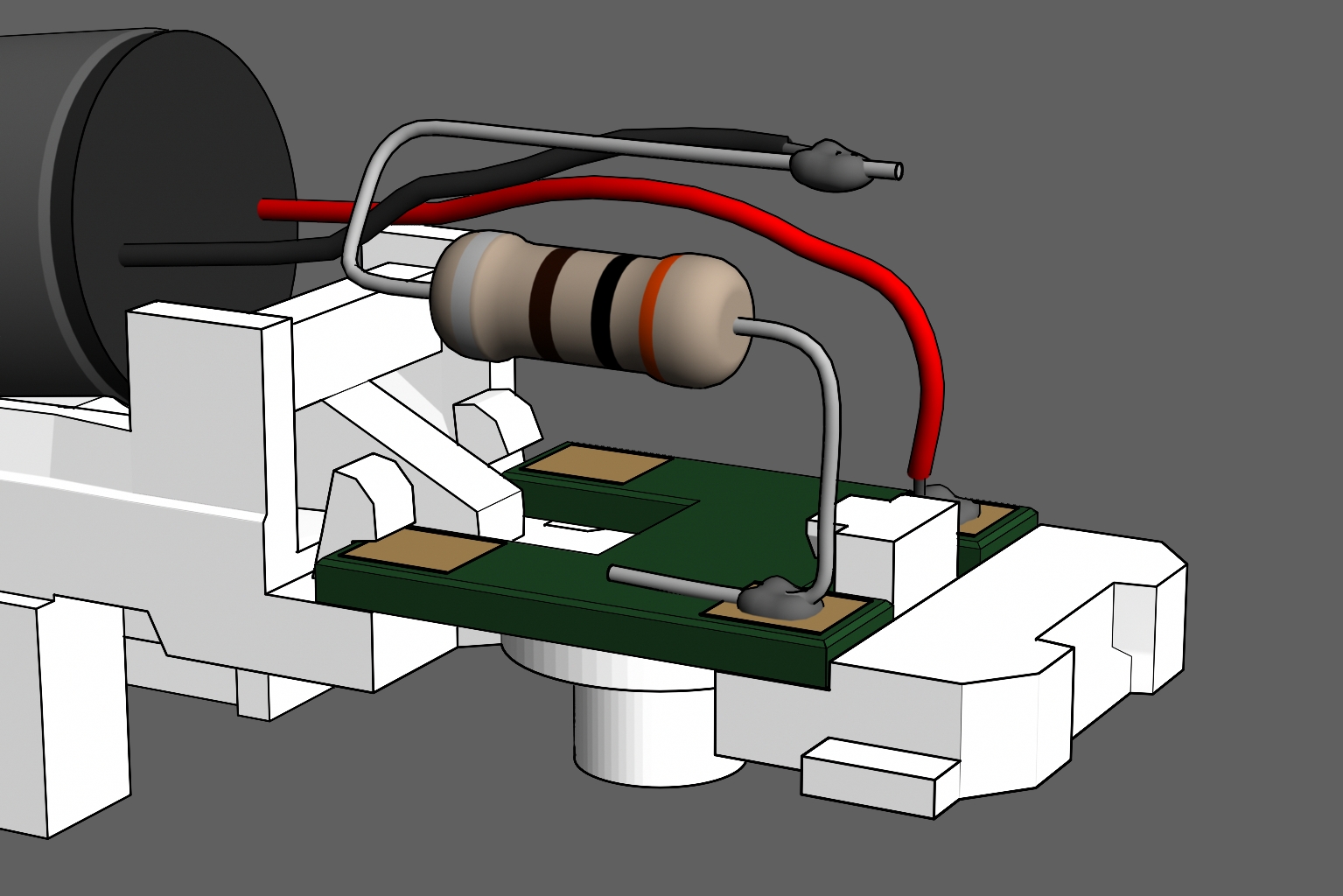
Step 11
Use the resistor from the handrail kit for this step.
1. Cut the resistor's leads on each side to 1/2 inch. Bend the leads into an "S" shape as seen in the image.
2. Solder the resistor to the circuit board where the black wire was originally attached.
3. Solder the black wire to the other end of the resistor.
No handrail kit? Use any brand resistor (330 Ohm 1/4 Watt 5% is recommended)

Step 12
Use the wires from handrail kit in this step.
Solder a wire to each of the electrical pickups on the motorized truck. Solder one wire per pickup.
No Handrial kit? Cut two pieces of 30AWG super flexible wire to 2 1/8 inches. Don't use wrapping wire, it is too stiff.

Step 13
1. Insert the black gear back into the truck.
2. Slip the wires into the frame past the worm gear.
3. Push the truck up into the frame.

Step 14
1 .Push the pin through the frame, through the truck, and through the gear until it sits evenly across the frame.
2. Make sure the truck can freely rotate without any resistance. If it is stiff, push the pin out and pry open the frame slightly with a screw driver. Double check solder on the pickups is not jamming the truck. If so, sand down the excess solder.

Step 15
Solder the wire ends to the unused copper terminals on the circuit board. Solder the left hand wire to the left terminal and right hand wire to the right hand terminal.

Step 16
Form a half loop with the wire coming from the truck and insert the wire into the notch by the motor clamp. A dab of CA glue will hold the wire permanently in the notch, if desired.
NOTE: The half loop in the wire is important because it provides enough slack to allow the truck to rotate freely.

Wiring Complete
At this point, the second truck can be mounted onto the frame. The locomotive is ready for a test run around the track.

Step 17
Thoroughly wash the 3D printed trucks and fuel tanks with Dawn dish washing detergent. Scrub with a tooth brush to remove any wax material. Use caution, the parts can snap off the sprue while scrubbing.

Step 18
Spray a coat of primer on the front of the sprue (the side with details). Don't prime or paint the bask sides.
Tamiya Surface Primer For Plastic and Metal is highly recommended. After painting, finish with a matte clear coat.

Step 19
Snap off the faux truck sides from the sprue. Take note of the flange on the backside (highlighted in blue).

Test Fit
The flange will guide the faux truck side into place. When properly attached, the flange will lay flat against the bottom of the truck.

Step 20
Use CA glue to attach all four truck sides.

Step 21
Snap the fuel tank into place. Glue is optional. There are left and right fuel tanks. Orient the fuel tanks so the the fuel cap is at the rear of the tank.
Assemble the Shell

Step 1
There are two pilot holes on the sides of the the rear cab door. Using a #80 drill bit (.0135"), drill the holes through so the cab handrails can be inserted and glued into place.

Warning!
The handrails can make painting certain paint schemes very difficult. You may choose to glue the handrails after masking and painting multiple colors on the body.
To preserve a good surface to glue the handrails, mask the areas highlighted in blue before priming and painting.

Step 2
1. Carefully cut the cab walkway hand rails off the fret (circled in red). Only cut where the arrows are pointing in the image.

Step 3
Bend the hand rails 90 degrees upward from the rectangular step. There is a slight depression next to the step to make bending easier.

Step 4
1. Without adding glue, insert the handrails into the holes by the door.
2. Use CA glue to attach the step to the notch above the stair case.
3. Add glue to the inside of the cab to secure the handrails through the drilled holes.

Step 5
Apply CA glue or epoxy to any side of the shell and attach the corresponding hand rail section. Repeat until all sides are attached. Be sure you are gluing the undecorated backside of the handrails to the shell. The etched details should face outward.
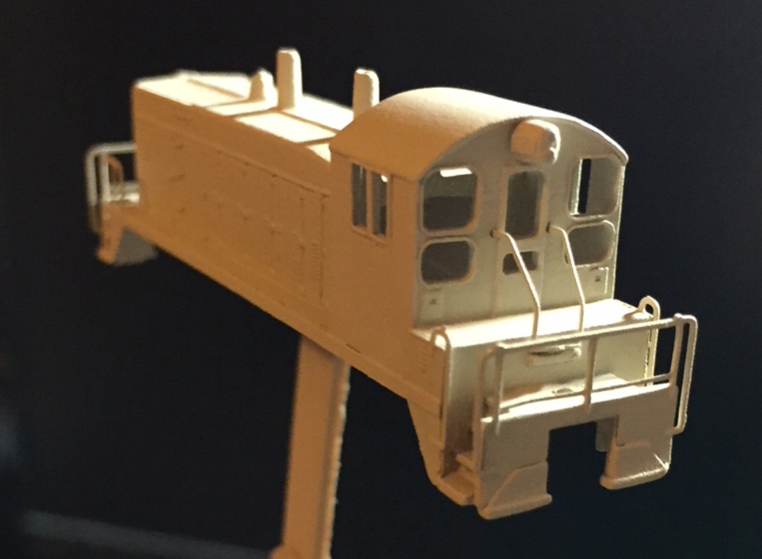
Step 6
1. Apply an even coat of primer to the entire shell.
2. Sand the shell with a high grit sand paper (3600 to 4000) to smooth the surface and hide 3D print lines. The handrails are fragile. Take care not to damage them while sanding the shell.
A second coat of primer may be required after sanding. The shell is ready to be painted in your preferred livery.

Step 7
After painting is complete, push the shell on to the frame. Friction will hold the shell onto the frame tightly.
Couplers: Micro Trains (MTL) 905 Body Mounted Couplers will fit snugly in the pilot hole. To use the screws that come with the couplers, the small hole above the pilot will need to be threaded with the MTL tap kit.
NOTE: The couplers must be taken out first to remove the shell. There are notches at the front and back of the frame to help remove the frame from the shell with a small screw driver.
Questions? Comments? Contact me at thezmaker@gmail.com