Basic SW1500 Instructions
Questions? Contact me at thezmaker@gmail.com
Tools & Parts Needed
Rokuhan Shorty Shinkansen Type (product # SA002-1 ) x 1
Flat Head Screw Driver (5/64 or 3/32)
Phillips Head Screw Driver (#0)
Needle Nose Pliers
Standard Flat Surface Pliers
Soldering Iron
Primer for metal
Recommended Tools
Handrail Kit with Wires and Resistor (Basic frame wire kit sold here)
Wire Stripper made to strip 30 AWG wire
Tamiya Surface Primer for Plastic and Metal (works equally well for the shell, frame, fuel tanks and truck parts)
Micro Trains Tap and Drill set for coupler mounting
Metal Files for smoothing out print lines if desired
Running the locomotive (Basic frame with single shorty)
Use 9 volts or less to run the locomotive if installing the resistor. Use a PWM type of throttle for best results. If you don’t install the resistor, use 1.5 to 3 volts max.

Prep the Shorty First!
If you have not already done so, follow all steps in the “Shorty Prep” page to prep the motor and trucks. Then return to this page to begin constructing your SW1500.
Click the green button below.
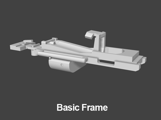
The Basic Frame
It may have fewer features than the advanced frame but it is still an improvement over the SW1200. The front wheel drive configuration of the basic frame combined with the heavier shell of the SW1500 provides excellent pulling power. Also, the basic frame’s open design makes mounting the circuit board and soldering the wires easier than the SW1200.
The first thing to do is to check the overall condition of the 3D print. Follow the steps below to begin.

Clean it first
Clean the brass shell, frame and handrails with rubbing alcohol. Scrub the shell and frame with a tooth brush to remove the anti-tarnish coating applied by the factory. The handrails can be placed in an alcohol bath without scrubbing. Dawn dish detergent works as an alternative to alcohol. Wait for the parts to be completely dry before moving on.
NOTE: Print lines can be exaggerated by the reflective properties of the brass. The majority of print lines will disappear after the first coat of primer or paint.

Check Print Integrity
Due to the metal casting process, even a good print can be slightly out of shape. Inspect the model and verify all major surfaces are straight and flat. Print lines are unavoidable and do not disqualify a good print. The goal here is make sure the model is square and not warped. Some common areas to check are listed below.

The Frame
The frame has much less mass in the rear area (circled in red) compared to the front. This area can be bent during printing, tumbling, or shipping. Make sure the frame is straight. If it is misshapen, use pliers to straighten it.

Test Fit
Test the fit of the frame into the shell. In future steps, there will be a layer of primer on the frame and the shell. The primer can make the shell fit the frame VERY tight. If the fit is very tight before applying any paint/primer, pry open the shell slightly or sand down some of the inner surfaces to loosen the fit.
Assemble the Motor and Frame
Step 1
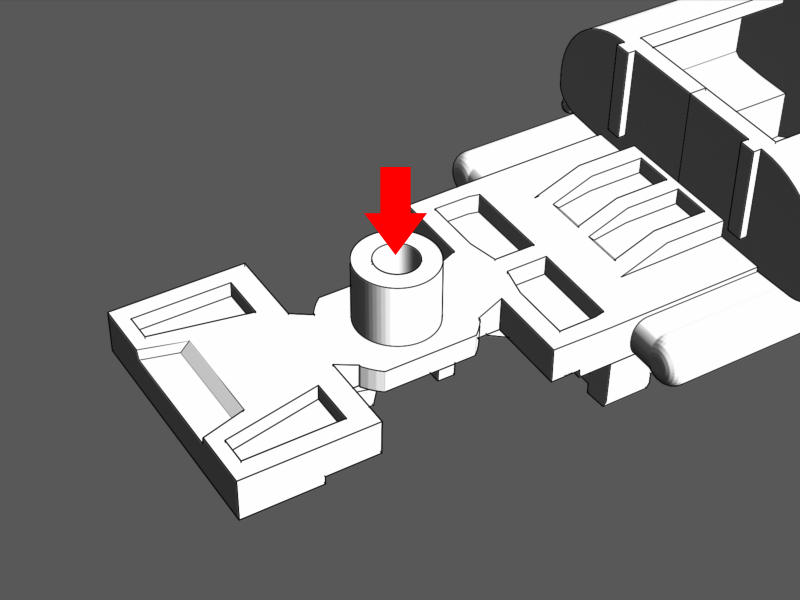
Locate the hole under the frame that will hold the Shorty's truck screw.
Attempt to screw in the shorty’s screw to see if it locks into place.
If the screw does not enter the hole by simply turning it with a screw driver, use a #00-90 tap to thread the hole for the screw.
NOTE: Due to variations in brass printing, some frames will allow the screw to work without drilling or tapping.

Step 2
Apply a coat of primer to the frame. Use primer intended for metal and be sure it is compatible with the paint you will use. For best results, use an air brush or any spray can with a fine mist tip.
As you work on the frame in later steps, it is normal for some primer to be scratched off.

Step 3
After the primer coat has dried and cured.
Insert the shorty motor into the frame. If the motor does not fit pull open the frame clamp slightly.

Step 4
Place the motor exactly as depicted in the illustration. Looking at the frame from behind, the red wire will be on the right.
Make sure the motor is pushed as far forward as the frame will allow.
Push down on the frame clamp to lock the motor in place.

Step 5
Cut the black wire from the circuit board.
Insert the circuit board under the clamp arm and slide it into place. Push the board down into the fame.

Step 6
It should lay flat and even in the frame. Don’t close the clamp arm until you are sure the board fits perfectly in place.
NOTE: Some shorty circuit boards are not perfectly “H” shaped. Use a file or sand paper to open up the notches so it will fit.

Step 7
Push down the clamp arm to lock the circuit board into place.

Step 11
Use the wires from handrail kit in this step.
Solder a wire to each of the electrical pickups on the motorized truck. Solder one wire per pickup.
No Handrial kit? Cut two pieces of 30AWG super flexible wire to 2 1/8 inches. Don't use wrapping wire, it is too stiff.

Step 12
1. Insert the black gear back into the truck. Arrange the truck so that the side with the chopped off coupler box is facing the fuel tank (This will leave extra room for the couplers).
2. Slip the wires into the frame past the worm gear.
3. Push the truck up into the frame.

Step 13
1 .Push the pin through the frame, through the truck, and through the gear until it sits evenly across the frame.
2. Make sure the truck can freely rotate without any resistance. If it is stiff, push the pin out and pry open the frame slightly with a screw driver. Double check solder on the pickups is not jamming the truck. If so, sand down the excess solder.

Step 14
Use the resistor from the handrail kit for this step.
1. Cut the resistor's leads on each side to 1/2 inch. Bend the leads into an "S" shape as seen in the image.
2. Solder the resistor to the terminal nearest to the motor on the left side (opposite the red wire).
No handrail kit? Use any brand resistor (330 Ohm 1/4 Watt 5% is recommended)

Step 15
Solder the black wire to the other end of the resistor.

Step 16
1. Position the wires from the front truck so they reach to the rear of the circuit board.
2. Solder the wire ends to the unused copper terminals on the circuit board.
Do not cross the the wires from the truck. Solder the left hand wire to the left open terminal and right hand wire to the right hand terminal.

Step 17
Place the other truck onto the frame.
Arrange the truck so that the side with the chopped off coupler box is facing the fuel tank (This will leave extra room for the couplers).
Tighten the shorty’s screw into place to hold the truck onto the frame.

Wiring Complete
Congrats! The locomotive frame is ready for a test run. Go back to the previous page for instructions on assembling the shell and adding the truck details.