TR4B Calf Instructions
Questions? Contact me at thezmaker@gmail.com
Tools Needed
Flat Head Screw Driver (5/64 or 3/32)
Phillips Head Screw Driver (#0)
Needle Nose Pliers
Standard Flat Surface Pliers
Soldering Iron
Primer for metal
Recommended Tools
Handrail Kit with Wires and Resistor (sold here)
Wire Stripper made to strip 30 AWG wire
Tamiya Surface Primer for Plastic and Metal (works equally well for the shell, frame, fuel tanks and truck parts)
Micro Trains Tap and Drill set for coupler mounting
Metal Files for smoothing out print lines if desired
#00-90 Tap and Drill (only needed if the screw from the shorty does not fit into the frame at step 4)
Running the locomotive
Use 9 volts or less to run the locomotive if installing the resistor. Use a PWM type of throttle for best results. If you don’t install the resistor, use 1.5 to 3 volts max.

Prep the Shorty First!
If you have not already done so, follow all steps in the “Shorty Prep” page to prep the motor and trucks. Then return to this page to begin constructing your TR4B Calf.
Click the green button below.

3D Printed Brass Models
Brass prints are printed in wax and then cast in metal. All brass parts are put into a tumbler to improve the surface. However, the tumbler's smoothing medium cannot reach some areas of the print. Use metal files before painting to smooth rough surfaces. Another good time to sand down the rough areas is after the first coat of primer.
Check Print Integrity
Due to the metal casting process, even a good print can be slightly out of shape. Inspect the model and verify all major surfaces are straight and flat. Print lines are unavoidable and do not disqualify a good print. The goal here is make sure the model is square and not warped. Some common areas to check are listed below.

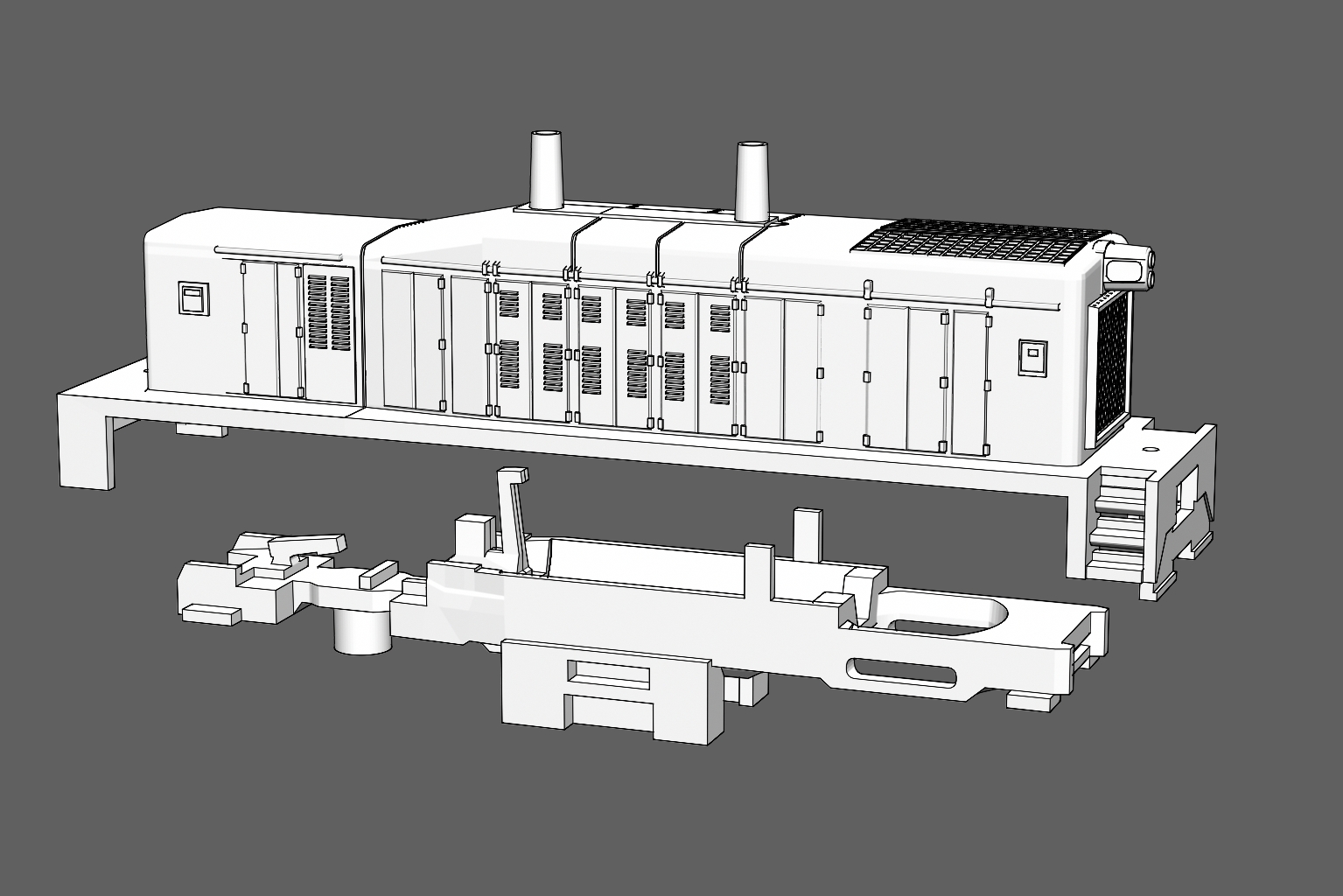
The Frame
The frame has much less mass in the rear area (circled in red) compared to the front. This area can be bent during printing, tumbling, or shipping. Make sure the frame is straight. If it is misshapen, use pliers to straighten it.
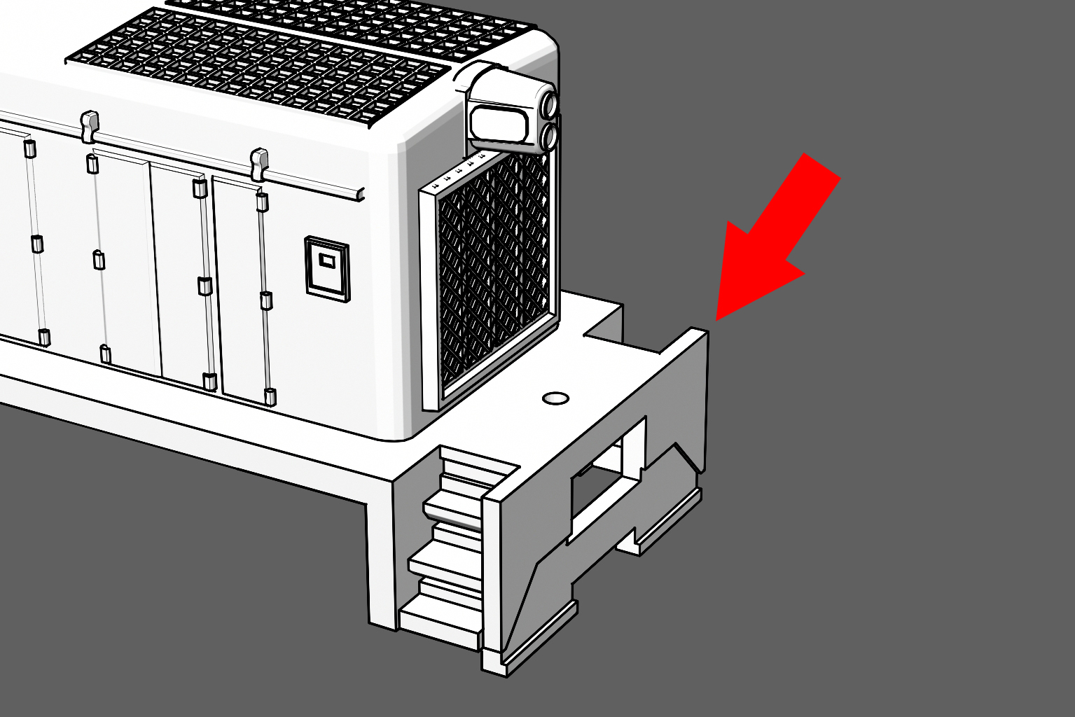
Pilot Wall
The wall between the pilot and the stair case can be slightly bent during the smoothing process. It can be put back into shape with needle nose pliers. The etched metal handrails will be glued to the pilot wall so make sure it is square.

Test Fit
Test the fit of the frame into the shell. The shell may need to be pried open a slight amount to allow the frame to fit into it. Notice the four tabs on the four corners of the frame (circled in red). This is the resting place for the shell. Do not push the shell past the tabs.
Begin Assembly

Clean it first
Clean the brass shell, frame and handrails with rubbing alcohol. Scrub the shell and frame with a tooth brush to remove the anti-tarnish coating applied by the factory. The handrails can be placed in an alcohol bath without scrubbing. Dawn dish detergent works as an alternative to alcohol. Wait for the parts to be completely dry before moving on.

Trimming the Circuit Board and Truck Pin
As seen in the illustration, the truck pin and the circuit board are wider than the frame and will not fit under the calf’s shell. Use tin snips to cut the circuit board and the pin.

Step 1
Cut off any wires and remove old solder from the printed circuit board (PCB).

Step 2
Measure 0.03 inches (0.75 mm) from the long side of the printed circuit board (PCB) and mark it with a pen or pencil. The white lines in the illustration show where to cut. Using heavy tin snips, cut thin slices away until the measured area is completely removed from both sides of the PCB.
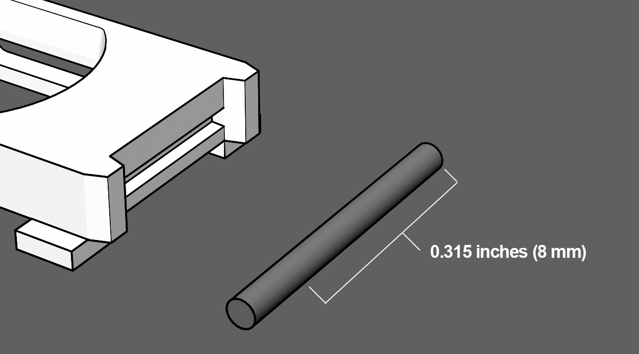
Step 3
The truck pin must be cut down to 0.315 inches (8 mm) to fit under the shell. Use caution, the pieces can go flying across the room when cutting. Consider using safety glasses during this step.
TIP: A good trick is to fold a one inch piece of tape around half the pin (like a flag) before cutting. That way it is easy to to find if it falls off your work station.

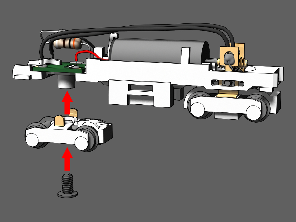
Step 4
Locate the hole under the frame that will hold the Shorty's truck screw.
Attempt to screw in the shorty’s screw to see if it locks into place.
If the screw does not enter the hole by simply turning it with a screw driver, use a #00-90 tap to thread the hole for the screw.
NOTE: Due to variations in brass printing, some frames will allow the screw to work without drilling or tapping.

Step 5
1. An optional step is to mask the area where the fuel tank will be attached(seen in blue).
2. Apply a coat of primer to the frame. Use primer intended for metal and be sure it is compatible with the paint you will use. For best results, use an air brush or any spray can with a fine mist tip.

Step 6
After the primer coat has dried and cured.
Insert the circuit board under the clamp arm and slide it into place. Push the board down into the fame. It should lay flat and even in the frame. Don’t close the clamp arm until you are sure the board fits perfectly in place.
NOTE: Some shorty circuit boards are not perfectly “H” shaped. Use a file or sand paper to open up the notches so it will fit.

Step 7
Inspect the circuit board’s fit. If it hangs over the frame, remove it from the frame and file down the edges with sand paper.
Be absolutely sure the board lays perfectly flat against the frame.
Test fit the shell to see if the circuit board is not in the way.

Step 8
Push down the clamp arm to lock the circuit board into place.

Step 9
Insert the motor into the cradle. The red wire goes on the right side. Looking at the frame from the rear, the red wire will be on the right hand side of the frame.

Step 10
There are tabs on each side of the motor and a clamp at the rear. Push all three inward until they hold the motor firmly in place.

Step 11
Use the wires from handrail kit in this step.
Solder a wire to each of the electrical pickups on the motorized truck. Solder one wire per pickup.
No Handrial kit? Cut two pieces of 30AWG super flexible wire to 2 1/8 inches. Don't use wrapping wire, it is too stiff.
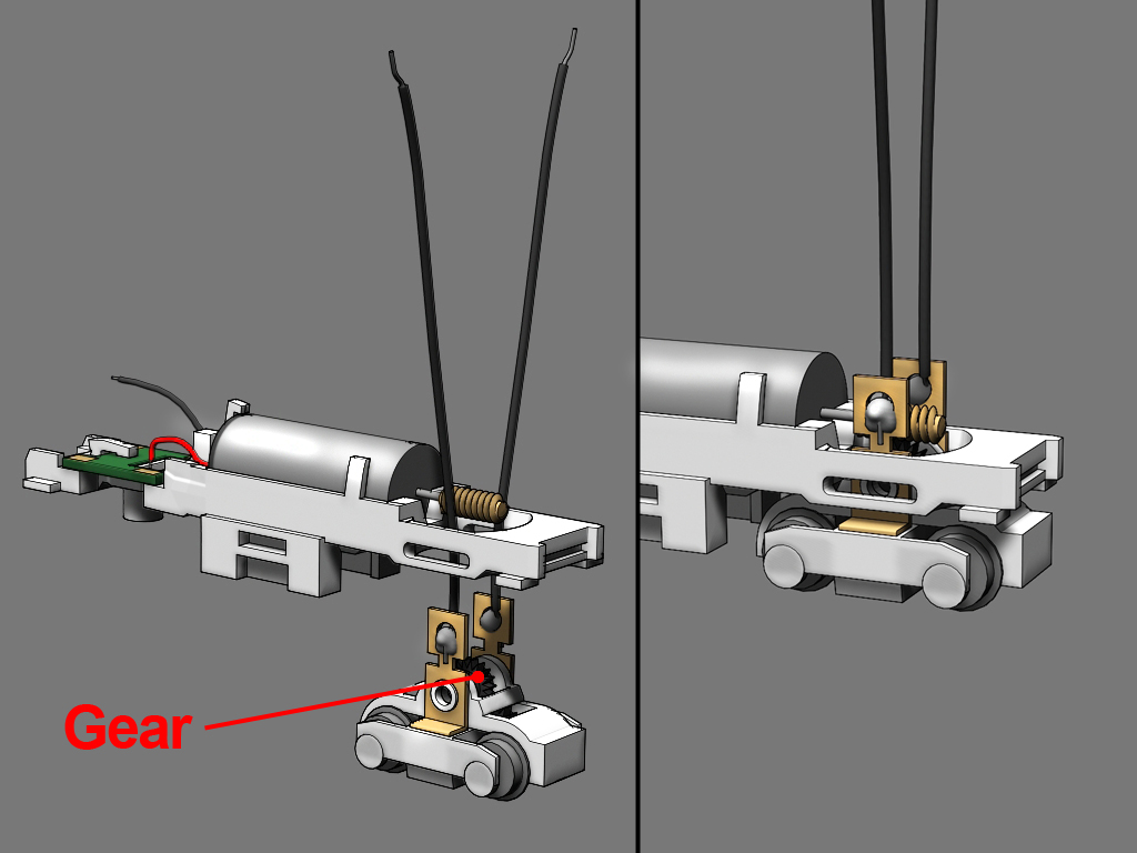
Step 12
1. Insert the black gear back into the truck.
2. Slip the wires into the frame past the worm gear.
3. Push the truck up into the frame.

Step 13
1 .Push the pin through the frame, through the truck, and through the gear until it sits evenly across the frame.
2. Verify the pin does not hang outside the frame.
3. Make sure the truck can freely rotate without any resistance. If it is stiff, push the pin out and pry open the frame slightly with a screw driver. Double check solder on the pickups is not jamming the truck. If so, sand down the excess solder.

Step
14
Solder the red wire to the nearest right hand terminal on the circuit board.

Step 15
Use the resistor from the handrail kit for this step.
1. Cut the resistor's leads on each side to 1/2 inch. Bend the leads into an "S" shape as seen in the image.
2. Solder the resistor to the terminal nearest to the motor on the left side (opposite the red wire).
No handrail kit? Use any brand resistor (330 Ohm 1/4 Watt 5% is recommended)

Step 16
3. Solder the black wire to the other end of the resistor.

Step 17
1. Position the wires from the front truck so they reach to the rear of the circuit board.
2. Solder the wire ends to the unused copper terminals on the circuit board.
Solder the left hand wire to the left terminal and right hand wire to the right hand terminal.
Step 18
Place the other truck onto the frame.
Tighten the shorty’s screw into place to hold the truck onto the frame.
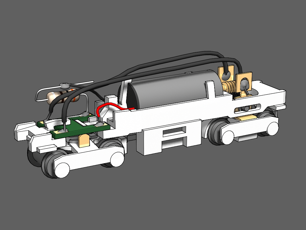
Wiring Complete
The locomotive frame is ready for a test run.

Step 19
Thoroughly wash the 3D printed trucks and fuel tanks with Dawn dish washing detergent. Scrub with a tooth brush to remove any wax material. Use caution, the parts can snap off the sprue while scrubbing.

Step 20
Spray a coat of primer on the front of the sprue (the side with details). Don't prime or paint the bask sides.
Tamiya Surface Primer For Plastic and Metal is highly recommended. After painting, finish with a matte clear coat.

Step 21
Snap off the faux truck sides from the sprue. Take note of the flange on the backside (highlighted in blue).

Test Fit
The flange will guide the faux truck side into place. When properly attached, the flange will lay flat against the bottom of the truck.
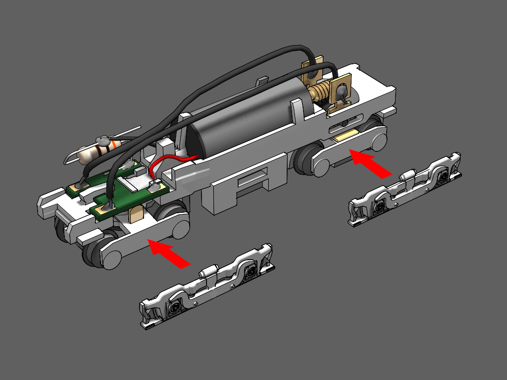
Step 22
Use CA glue to attach all four truck sides.
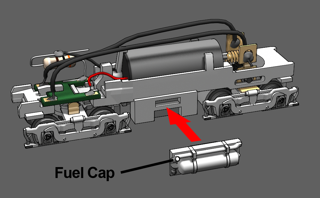
Step 23
Snap the fuel tank into place. Glue is optional. There are left and right fuel tanks. Orient the fuel tanks so the the fuel cap is at the rear of the tank. The fuel cap should be next to the unpowered truck.
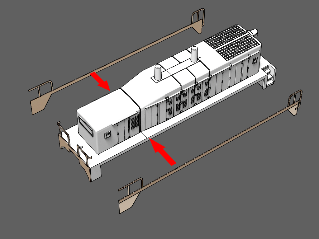
Assemble the Shell

Warnings
The handrails can make painting certain railroad paint schemes very difficult. You may choose to glue the handrails after masking and painting multiple colors on the body.
To preserve a good surface to glue the handrails, mask the areas highlighted in blue before priming and painting.

Choose a Handrail Set
There are four different handrail sections on the sprue that fit the front and rear of the shell. Choose the set of handrails that match the real locomotive you are modeling.

Step 1
Carefully cut out the rear handrail section of your choosing. This section will be glued to the shell first to make it easier to attached the side handrails in a later step.
NOTE: You may want to prime and paint these parts before gluing them to the shell. Don’t paint the areas where glue will be applied.

Step 2
There is a tab at the outer end of the handrail.
Locate the indented line the red arrow is pointing to in the illustration.
At that line, bend the tab 90 degrees backward as seen in the illustration.

Step 3
Attach the rear handrail section to the shell using epoxy or CA glue.
Step 4
Cut the side hand rail sections from the sprue and attach them to the walkways of the shell with CA glue.
NOTE: Be sure the flat backside of the handrail is glued to the shell. The front of the handrails sections have visible etched details.

Step 5
Solder the bent tabs on the rear section handrails where they meet the side handrails. It is highly recommended the tabs be soldered but they can be joined by CA glue if desired.
Gently file away any excess solder.

Step 6
Attach the front handrail section to the shell.
If you have not painted the shell yet,
1. Apply an even coat of primer to the entire shell.
2. Sand the shell with a high grit sand paper (3600 to 4000) to smooth the surface and hide 3D print lines. The handrails are fragile. Take care not to damage them while sanding the shell.
A second coat of primer may be required after sanding. The shell is ready to be painted in your preferred livery.

Step 7
After painting is complete, push the shell on to the frame. Friction will hold the shell onto the frame tightly.

Finishing Up
Add Couplers: Micro Trains (MTL) 905 Body Mounted Couplers will fit on the shell. Use the mounting screws that come with the couplers. The small hole above the pilot will need to be threaded with the MTL tap kit.
Questions? Comments? Contact me at thezmaker@gmail.com