GE 44 Instructions
Questions? Contact me at thezmaker@gmail.com
Parts Needed
Shell and Chassis (sold here)
Trucks and Motor Clip (sold here)
Electronic Kit (sold here)
6x15mm 12 volt motor from Tramfabreik item 0615S (sold here)
Rokuhan Shorty Chassis B Shinkansen (available at your favorite Z Scale retailer).
Tools Needed
Gear Puller (Any gear puller that can handle 0.8mm to 1mm motor shafts)
Flat Head Screw Driver (5/64 or 3/32)
Phillips Head Screw Driver (#0)
Needle Nose Pliers
Standard Flat Surface Pliers
Additional Recommended Tools
Wire Stripper made to strip 30 AWG wire
Soldering Iron
Tamiya Surface Primer for Plastic and Metal (works equally well for the shell, frame, plastic truck parts)
Metal Files for smoothing out print lines if desired
IMPORTANT!!
This model is compatible only with the “Shorty B Shinkansen” type. Some parts will not fit other Shorty models.
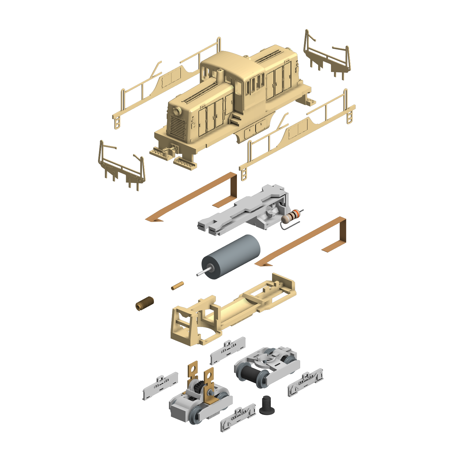
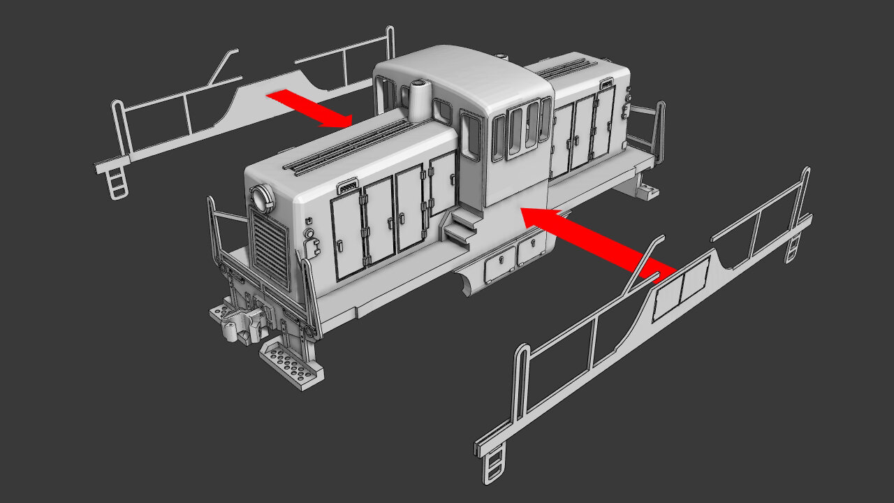
Parts Overview
Part 1 - Disassemble The Shorty

Prep The Shorty
If you have not already done so, follow all steps in the “Shorty Prep” page to prep the motor and trucks. Then return to this page to begin constructing your 44 Tonner.
Click the green button below.
Part 2 - Check the 3D print integrity
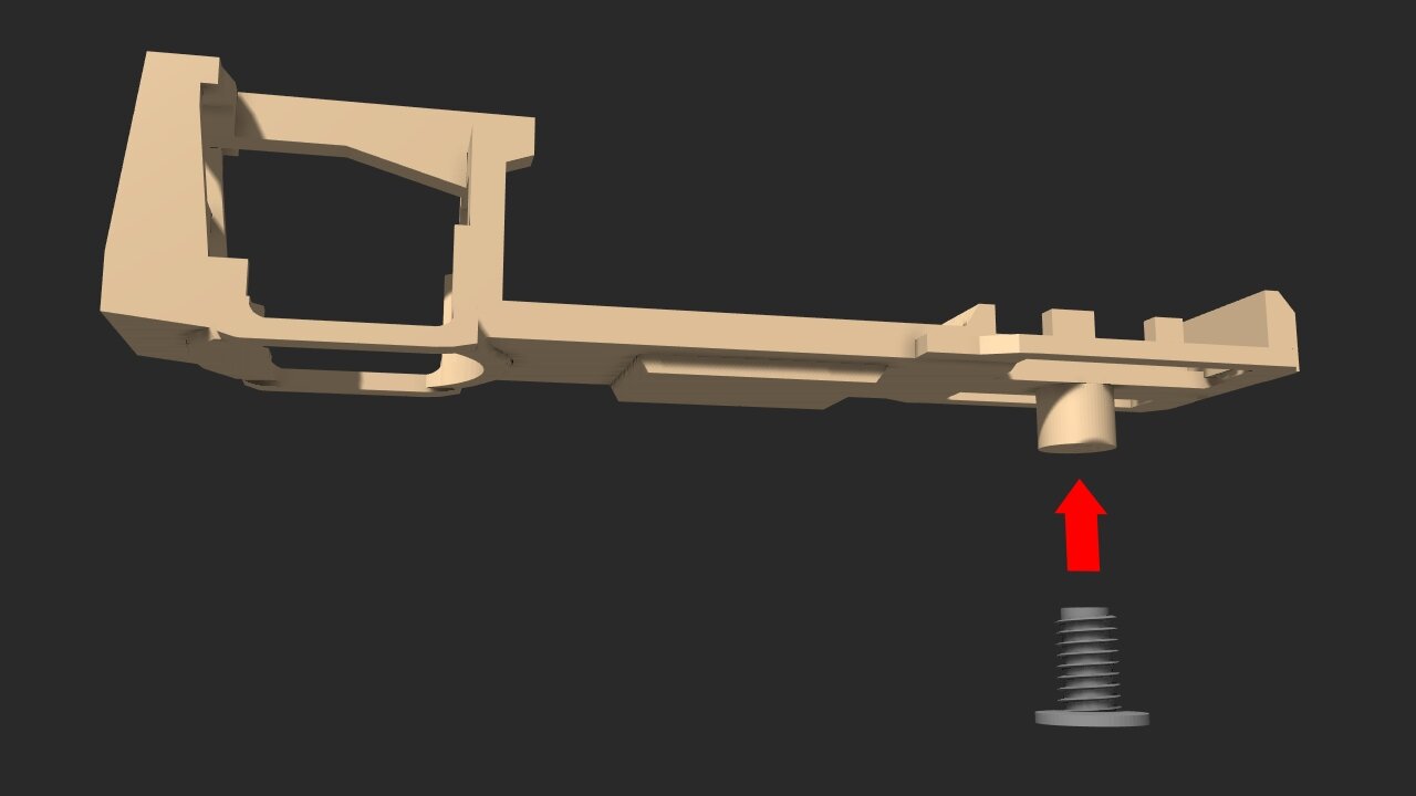
Test fit the screw
There is a hole under the chassis for a screw. The Shorty comes with a screw to hold the dummy truck in place.
Before moving on, test fit the screw in the hole.
If the screw turns a few times before tightening, your good to go. It does not need to screw in all the way.
If the screw does not fit, use a drill bit to expand the hole.
If there is NO hole at all, that is a print error and you will need to contact Shapeways and get a reprint.

Square up the Shell
During the finishing process of 3D printing, the foot boards may have been bent out of shape. Use pliers to gently reshape them.
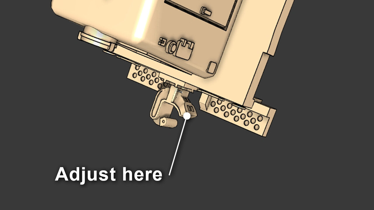
Adjust the coupler Opening
Like the foot boards, the couplers may have been bent out of shape. Test the coupler by mating it with an AZL or Full Throttle coupler. You can push snap either of those couplers and get a secure lock. If there is too much resistance, slightly open the coupler by bending the wall opposite of the knuckle. Avoid bending the knuckle unless it does not grasp the AZL/Full Throttle coupler.
NOTE: Micro Trains Z Scale couplers will mate with the 44 Tonner but they will have to be manually lifted and dropped into place. It is not capable of magnetic uncoupling.
Part 3 - Transplant The Worm Gear

Order Your motor
The best motor for your 44 Tonner locomotive is sold by Tramfabreik. They offer the only 12volt 6x15mm motor. These motors can be purchased at the Tramfabreik website and at their Ebay store.
Links:

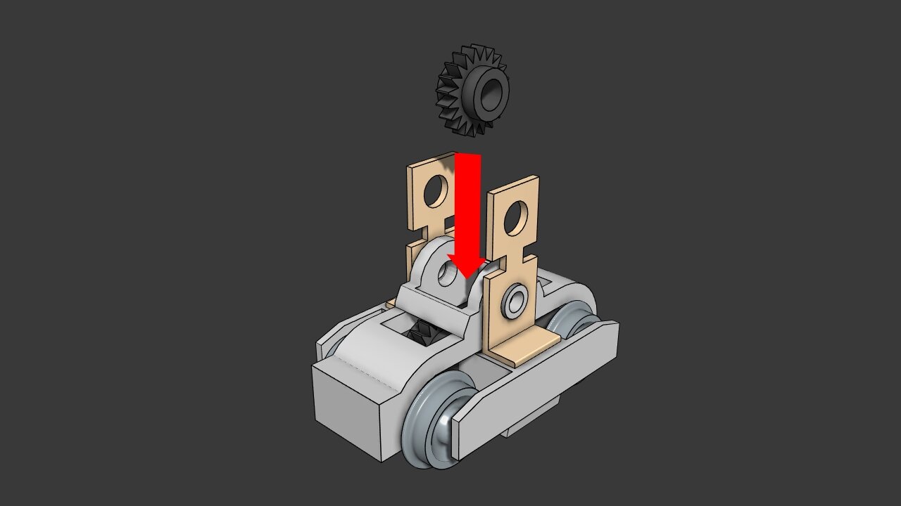
Removing the worm gear
The motor that comes with the shorty is too wide to fit into the 44 Tonner chassis. The worm gear needs to be taken from the shorty motor and attached to the Tramfabreik motor.
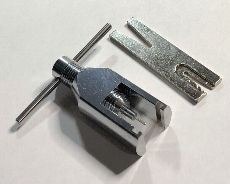
Set up the gear puller
Be sure your gear puller can handle 1mm motor shafts. If your gear puller has multiple pins, install the 1mm pin.

Step 1
Insert the Shorty’s motor shaft into the gear leveler.

Step 2
Align the pin with the motor shaft and rotate the handle to pull off the gear.

Step 3
The worm gear is now free from the motor shaft.
Next, insert one of the two shaft adapters from the Finishing Kit as far as it will go. Usually it will only go in a small distance as seen in the lower photo.
NOTE: Two shaft adapters are included in case something goes wrong. Only one is needed to complete the model.

Step 4
Use a C-clamp to push the adapter into the worm gear. Do not over tighten. As long as 80% of the adapter is inserted, it will do the job.

It’s Ready To Mount
Make sure the openings at both ends of the gear/adapter are open. Try to mount the worm gear onto the 6x15mm motor’s shaft to test the fit.
If the fit is tight, then it’s ready to go.
If the gear is a bit loose, remove the gear, VERY SLIGHTLY squeeze the shaft adapter, then mount it again. Repeat if needed.
If it does not fit at all, use a hobby knife to open up the tube. If one of the ends is closed off, insert a small drill bit from the opposite side to reopen it.
NOTE: Moving forward, any mention of a motor is in reference to the 6x15mm Tramfabreik motor. The shorty motor can be discarded.

Adjusting the gear
Slide the gear onto the motor shaft until the it is about 1 mm (0.039 inches) from the motor’s main body. Do not include the shaft adapter when measuring.
Part 4 - Assemble the chassis

Separate The Finishing Parts
Cut off the sprue of truck details from the motor clip. If any flash remains on top of the motor clip, scrape it off.
The parts can be snapped apart if desired.

Cut the wires
Trim down the motor wires down to 12.5 mm (0.5 inches).
Use a wire stripper to prep the wires for soldering.
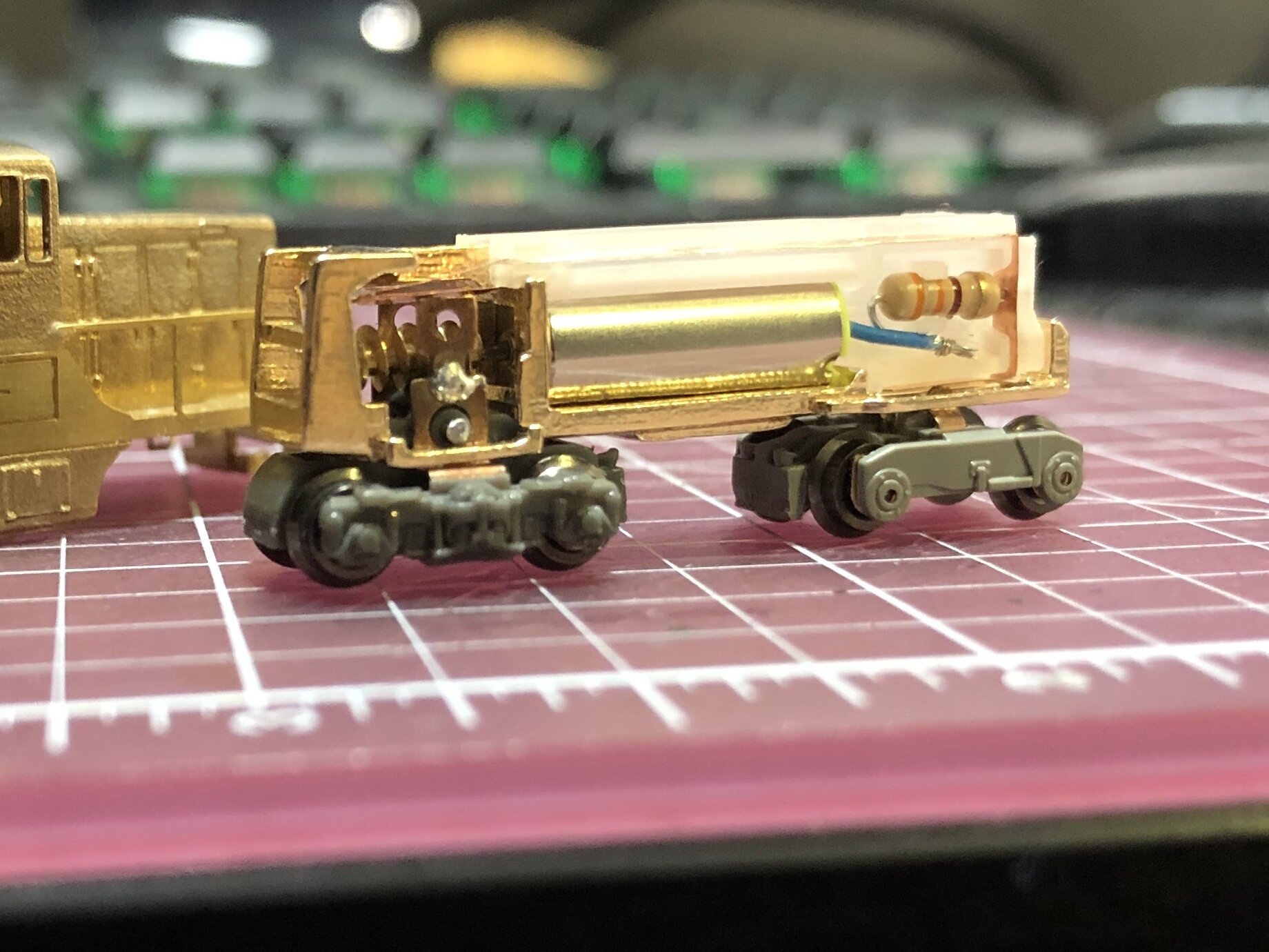
Motor Orientation
The gear cage is located the back of the chassis. The worm gear will be facing the rear of the chassis. The flat area is the front. Position the motor wires just as they are seen in the image.
IMPORTANT: The blue wire must be on the right side of the locomotive and the red wire must be on left side. This will insure the locomotive moves in the same direction as all other z scale locomotives.

Step 1
Slide the motor through the cage at the back of the chassis. Push through the cage and down until the motor clicks into place.
Step 2
Double Check Orientation
Be sure the wires are on the correct side. It should match the image. If not, remove the motor with a small flat head screw driver and rotate it to match the image.

Tip: Clear the Slots
Use a hobby knife to clear out any left over resin or wax build up that may be in the slots on the motor clip.
This will ensure the copper pickups will fit all the way into the slots.

Step 3
Gather the two copper pickups from the finishing kit.
Step 3A
The copper pickups are pre-shaped to fit into the slots that run along the side of the motor clip.
Slide a copper pickup into the slots on each side of the motor clip.

Step 3B
The copper pickups should not stick out the sides of the motor clip.

Step 4
Use a #80 or #76 drill bit to make a hole in the copper pickups.
Drill through each of the two holes seen at the front of the motor clip.
Step 4A
Use a fresh hobby knife to widen the hole.Twist the blade to make the hole wide enough to fit the resistor lead.
Do this for both sides.

Step 5
Take the resistor from the finishing kit.
Notice that one of the leads is bent 90 degrees. Cut the bent lead down to half and inch.
Cut the other to 1/4 inch.

Step 6
Insert the 1/4 inch lead through the hole in the copper pickup.
Snap the resistor into the resistor holder.

Step 7
Move the motor wires out of the way and push the clip assembly into place.

Step 8
Make sure the motor’s wires are not pinched by the motor clip.

Step 9
Solder together the blue motor wire and the 1/2 inch resistor lead.

Step 10
Tuck in the two soldered wires underneath the resistor holder.
Make sure they do not stick out or they may collide with the shell and cause an electrical short.

Step 11
On the other side of the chassis, twist the red wire tight and thread it through the hole in the copper pickup.
(If there is no hole, revisit step 4)
For best results, solder the wire to the copper pickup. Don’t hold the soldering iron to the chassis because the plastic will melt. Apply soldering flux to the copper pickup and quickly drop the molten solder into place.

Step 12
Grab the gear pin form the Shorty’s powered truck.
Cut the gear pin down to 7mm or 0.275 inches. Parts may fly. Wear safety glasses.
File down any sharp edges from the cut.
You can test the pin’s size by setting it in the wells under the shell. When the model is complete, these wells allow the pin/truck to rotate as the locomotive goes around a curve.
Step 13
Place the main gear into the powered truck.

Step 14
Insert the powered truck into the rear of the chassis.

Step 15
Insert the pin into the truck. Make sure the main gear is lined up to allow the pin through.

Step 16
Test the range of motion for the powered truck by rotating it left and right. Make sure the copper towers on the truck are making contact the with copper pickups at all times.
If not, remove the powered truck and slightly bend the copper pickups downward.
Replace the powered truck and make sure the pickups are in contact with the towers at all times.

Step 17
Tightly grasp the dummy truck on both sides. Use needle nose pliers to bend the copper poles toward the middle about 20 degrees.
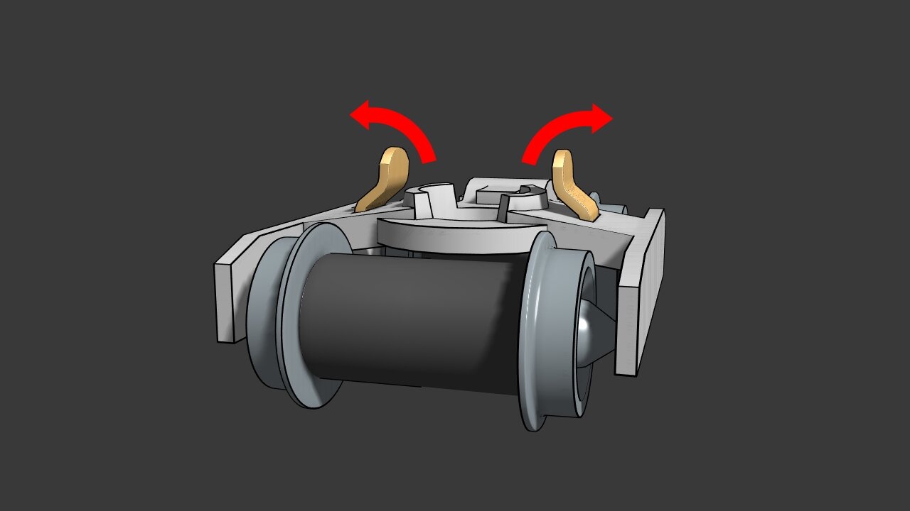
step 18
Half way up each pole, bend the pickups outward about 20 degrees to offset the previous bend.
This does not require extreme precision. As long as both poles are sitting at the same height after bending, they will do their job.

Step 19
Place the dummy truck on to the chassis and secure it with the shorty’s screw.
Part 5 - Assemble The Shell
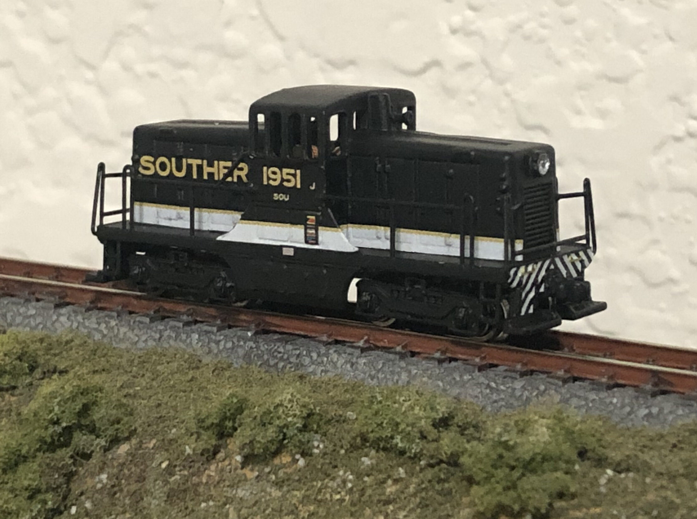
Painting & Decals
You must decide when to apply paint to your model based on the assembly steps. For example, your chosen paint scheme may be difficult to do with the handrails attached to the shell. Plan ahead if needed.
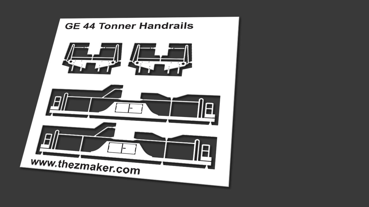
Step 1
Examine the 44 Tonner handrail set. If there is any tarnish, it can be cleaned with any house hold tarnish remover. If you don’t have any tarnish remover, ordinary ketchup can be used. Clean the handrails with Dial dish detergent or any cleaner that does not leave a chemical residue.

Step 2
Flip the handrail set over to view the back side.
In the blue areas seen in the image, use sand paper or a nail file to give the surface some tooth. Sanding the surface will enhance adhesion when these parts are glued to the shell.

Step 3
Sand the shell in the areas marked in blue with sand paper or nail file.

Step 4
Cut the front and rear hand rail sections from the sprue. They are identical so either one can be the front/rear.

Step 5
For both hand rail sections, bend the small upper bars back 20 degrees.

Step 6
Spread CA glue on the back of the hand rail sections and attach them to the front/rear of the shell. The ends of the small upper bars can be glued to the front of the long hood next to the grill.

Step 7
Cut the two handrail side sections from the sprue.

Step 8
Fold all four stirrup steps back and down 180 degrees.
Step 9
Spread CA glue on one side of the shell then attach one of the handrail sections. Repeat for the opposite side of the shell. The hand rail sections are identical so either part can be attached to either side of the shell.

Step 10
Snap off each truck detail from the truck sprue.

Step 11
Test fit the truck details on the sides of the Shorty’s trucks before gluing them.
When satisfied with the fit, attach the truck details with CA glue.
NOTE: The truck details will fit only if the Shorty trucks have been sanded smooth(as seen in the “Prep The Shorty” instructions).

Step 12
Slip the shell over the chassis. While the shell can fit on the chassis in either direction, the side with the horn is considered the front.
Part 5 - Finishing Up
-
-
-

Adding LED lights
The top of the motor clip has notches in it to allow connections to LED lights.