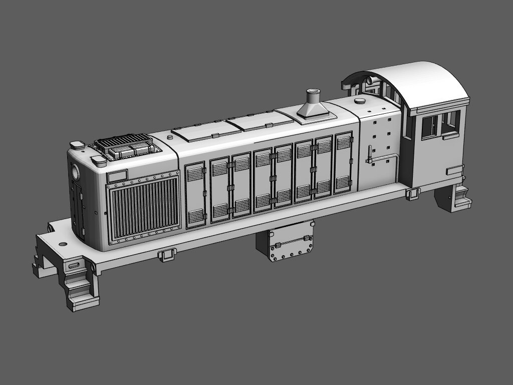
S-2 Instructions
Questions? Contact me at thezmaker@gmail.com
Tools Needed
Flat Head Screw Driver (5/64 or 3/32)
Phillips Head Screw Driver (#0)
Needle Nose Pliers
Standard Flat Surface Pliers
Soldering Iron
Primer for metal (Self Etching Primer is highly recommended)
Recommended Tools
Handrail Kit with Wires and Resistor (available here)
Wire Stripper made to strip 30 AWG wire
Tamiya Surface Primer for Plastic and Metal (works equally well for the shell, frame, plastic truck parts)
Micro Trains Tap and Drill set for coupler mounting
Metal Files for smoothing out print lines if desired
Running the locomotive
Use 9 volts or less to run the locomotive if the resistor is installed. Use a PWM type throttle for best results (sold here). If you don’t install the resistor, use 1.5 to 3 volts max.
DCC
These instructions show how to setup analog power but a DCC decoder can be installed if desired. Skip any step involving the electronic resistor. When you get to step 15, use the instructions from your decoder to determine the proper way to connect all the wires. Just remember that the shorty circuit board picks up power from the dummy truck. You will need to connect the circuit board to the DCC decoder in addition to the wires coming from the powered truck.
Lights
There are many ways to add lights to the locomotive. My preferred method is to use a circuit board that fits an AZL GP-38 or GP-30 in combination with fiber optic strands. There are also DCC boards that are designed to fit in an AZL GP-38 that will fit under the S-2’s hood. These boards can be wired directly to the motor and trucks during step 15 of the frame assembly section. Use tape or glue to mount the board on top of the motor/frame. The fiber optic strands can be inserted through the light holes on the shell and glued directly to the inner shell with white glue or wood glue. Use 1 mm or 1/2mm fibers. When shopping for fiber optics, look for single filament products that glow where cut or “end glow”.
Disassemble The Shorty
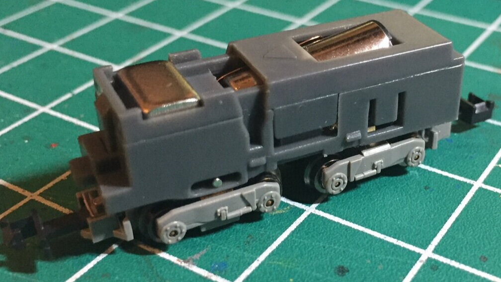
Prep The Shorty First
If you have not already done so, follow all steps in the “Shorty Prep” page to prep the motor and trucks. Then return to this page to begin constructing your S-2.
Click the green button below.
Inspection

About Brass 3D prints
Brass prints are printed in wax and then cast in metal. All brass parts are put into a tumbler to improve the surface. However, the tumbler's smoothing medium cannot reach some areas of the print. Use metal files before painting to smooth rough surfaces. Another good time to sand down the rough areas is after the first coat of primer.

Check Print Integrity
Due to the metal casting process, even a good print can be slightly out of shape. Inspect the model and verify all major surfaces are straight and flat. Print lines are unavoidable and do not disqualify a good print. The goal here is make sure the model is square and not warped. Some common areas to check are listed below.

The Frame
Using a ruler or hard edge, make sure the frame is square and in proper shape. Check sides to make sure the frame was not twisted during the metal casting process. Be sure the rear area with the large hole has straight even walls.

Rear Frame
Check the back end of the frame to be sure it has not been shifted out of place. The thin walls connecting the rear end can be easily bent sideways. If the rear end is misaligned, grasp the entire rear area and move it left or right into place.

Front Frame
The front part of the frame can be bent up or down during the printing process. Use pliers to straighten it if needed.

Stair Cases
The stair cases on the front and rear of the shell may be out of shape. Use pliers to make them square with the walk ways under the long hood.

Test Fit The Screw
Locate the hole under the frame that will hold the Shorty's truck screw. Due to variances in the art of casting brass, the screw may not thread well. It is possible to be too tight or not thread at all. If it is too tight, use a #00-90 tap to thread the hole for the screw. If the screw does not grip or is too loose, try adding putty around the inner walls.

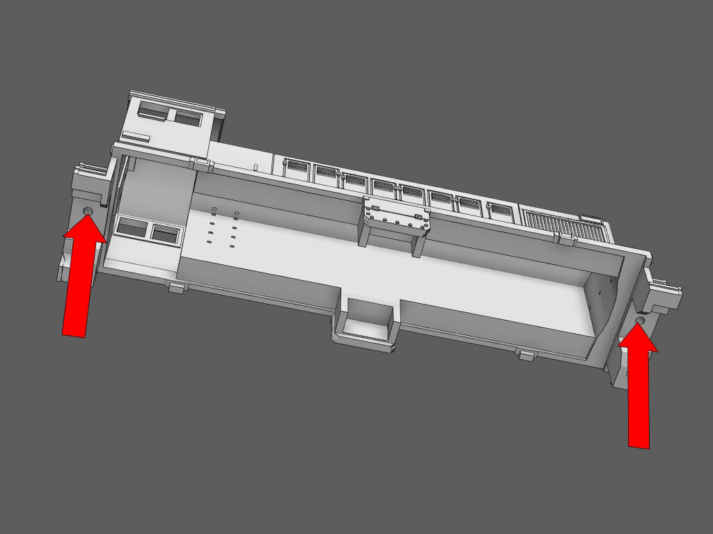
Test Fit the Frame
Test the fit of the frame into the shell. The shell may need to be pried open a slight amount to allow the frame to fit into it. Notice the tabs on the frame (circled in red). This is the resting place for the shell. Do not push the shell past the tabs.
The frame should slip into the shell without much force. If it does not, check for distortions in the parts. Bend the parts into shape with pliers or by hand.
Trouble with your print?
Is your print severely out of shape? Are there warped or dented areas? Shapeways guarantees quality prints. If your print appears damaged, or you simply have questions, contact the help desk; here.
Additional Shorty Preparation

Circuit Board
Unlike the SW1200 and SW1500, there are more steps needed to prepare the parts from the Shorty.
Cut the motor leads from circuit board. Make the cut where they connect to the solder to preserve as much wire as possible.
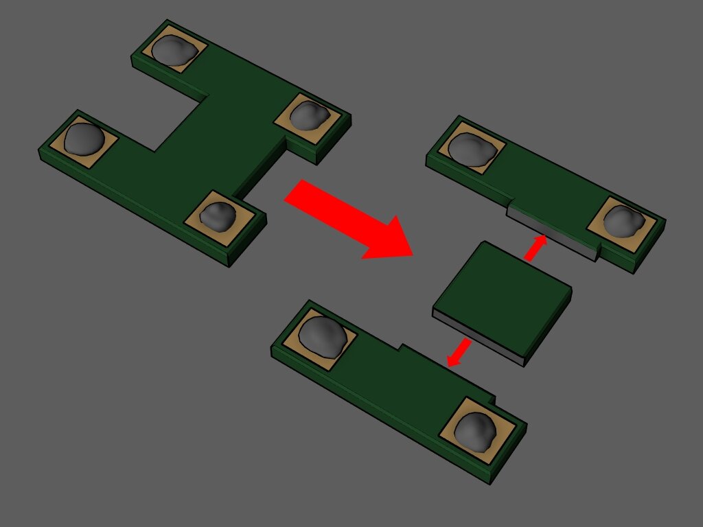
Cut The Circuit Board
With strong shears or a knife, cut off the two long sides of the circuit board. Discard the middle area. Smooth the cut surfaces with sand paper if needed.

Test Fit The Parts
Insert the circuit board pieces into the slots at the front of the frame. Do not glue them in place yet.
The cut area should be inserted first. The smooth outer edge should line up with the frame so that it fits inside the shell.

Insure a Proper Fit
Be sure the pieces of the circuit board fit all the way inside the frame. They must not protrude past the outer wall of the frame. The red line in the image shows where the frame meets with the inner part of the shell. If the pieces are too wide, file down the piece until it fits.
Leave the pieces in the frame for the next step.

Wiper Adjustment
The two copper wipers on the dummy truck need to be bent to accommodate the narrow space under the frame. Use needle nose pliers to bend the wipers about 15 degrees toward the middle.

Check The Clearance
With the circuit board pieces temporarily in place, mount the dummy truck onto the frame. Swivel the truck left and right to make sure the adjusted wipers have plenty of clearance. The truck should be able to rotate 30 to 35 degrees without touching the frame.
Adjust the wipers if needed.
When complete, remove the circuit board parts and dummy truck. Store them in a safe place.

Trim The Powered Truck
The powered truck has two tubes that hold the copper wipers in place. These tubes need to be trimmed to fit into the narrow space in the frame.
Leave the copper parts in place while trimming. Use a hobby knife to trim about 0.02 inch (.5 mm) off of both sides.

Strip Motor Leads
Strip the leads using a wire stripper that can handle 30AWG wire. You will need about 1/4 of an inch of exposed wire.
Cleaning and Surface Preparation

Remove Old Solder
For best results, the old solder should be removed from the circuit board parts.

Cleaning Brass Parts
Remove the circuit board parts and any other components.
Sand smooth the most outstanding print lines. Keep in mind most print lines will not be seen after the primer and paint are applied.
Clean the brass shell, frame and handrails with rubbing alcohol, vinegar, and/or Dawn dish detergent. Scrub the shell and frame with a tooth brush. Wait for the parts to be completely dry before moving on.

Prime The Frame
Apply a coat of primer to the frame.
Any “Self Etching” primer is highly recommended. It will adhere to the surface of the brass better than standard primer but it will take much longer to cure. Wait at least two days if a self etching primer is used. Read the instructions on the can to find out when the primer is cured. Some can take as long as 7 days.
Stuck waiting on the primer to cure? Skip to the “Assembling the Shell” section while the primer cures.
Assembling the Motor and Frame

Step 1
Insert the circuit board parts.
NOTE: The coat of primer is the main form of insulation to prevent short circuits. If you work carefully, the primer should be enough. However, you may want to add more insulating features to your frame.
TIPS: You could use CA glue around the edges and under the circuit boards. Or electrical tape under the circuit board where it makes contact with the frame. Whatever you do, be sure the wipers on the dummy truck are not blocked. The truck’s wipers must make contact with the bottom of the circuit board.

Step 2
With a screw driver or pliers, gently pry open the clip above the circuit board.
Open it just enough to fit the resistor into it.
NOTE: Prying open the clip also puts pressure on the circuit boards to hold them in place.

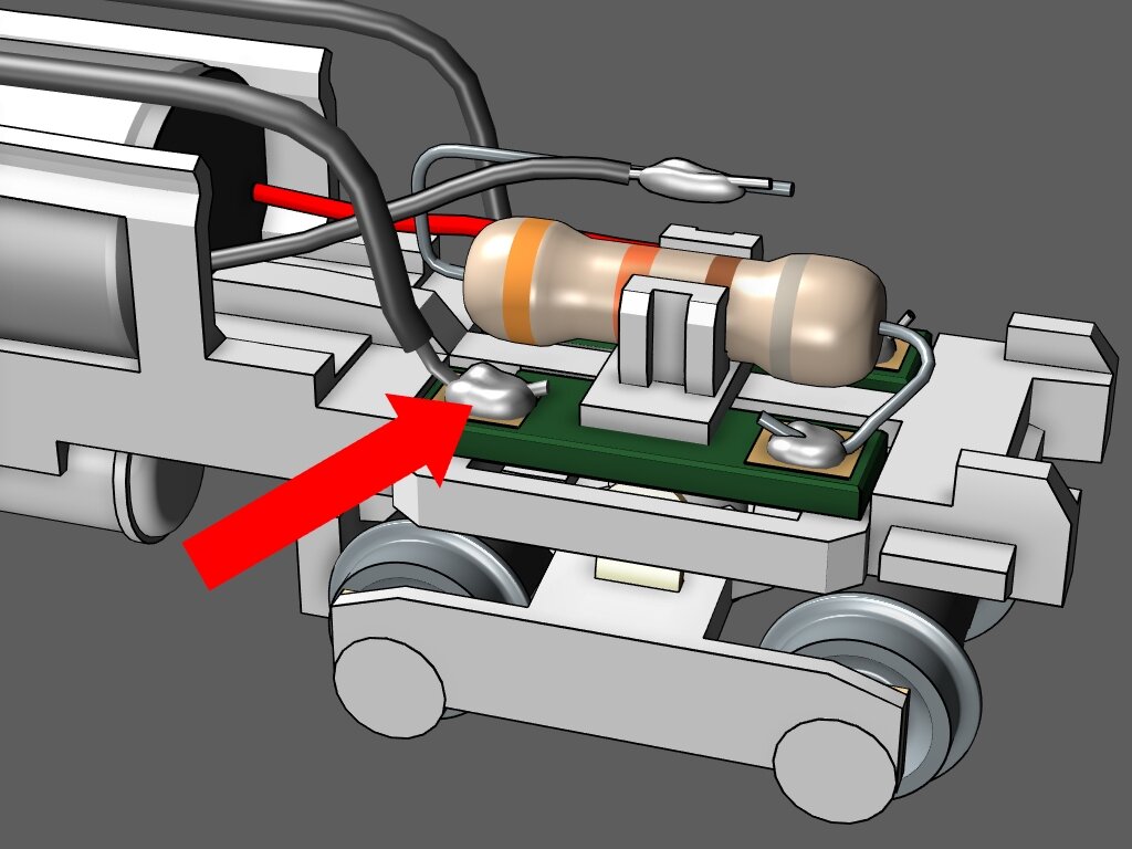
Step 3
A. Cut the leads on the resistor down to 1/2 an inch.
B. Bend the leads into an “S” shape like in the image.
C. Insert the resistor into the clip.

Step 4
Maneuver the front facing resistor lead so it makes contact with the right* metal tab on the circuit board.
*Right side of the frame, not the image.

Step 5
Solder the resistor lead to the metal tab on the circuit board. Don’t allow any solder to reach the frame.
Trim excess lead near the solder.

Step 6
Pry open the motor clip beams to allow the motor to fit through.

Step 7
Before placing the motor into the frame, study this image showing the motor in its proper orientation. Notice that the circuit board is at the front of the frame.
The black wire will be on the right side or engineer’s side of the locomotive.
If it were a boat, the black wire would be on the starboard side.

Step 8
Pass the worm gear through the opening in the frame and push the back end of the motor into place.

Step 9
Pinch the motor clip closed by hand. Then use pliers to lock the beams in place. Do not squeeze the motor with the pliers. The beams can be bent up and over the motor to lock it in place.
NOTE: The primer coat may get scratched during these steps. It is okay.

Step 10
Solder the black motor lead to the unconnected resistor lead.
Solder the red motor lead to an open terminal on the left side circuit board.

Step 11
Use the wires from S-2 handrail kit in this step.
Solder a wire to each of the electrical pickups on the motorized truck. Solder one wire per pickup.

Step 12
A. Insert the black gear back into the truck.
B. Slip the wires into the frame past the worm gear.
C. Push the truck up into the frame.
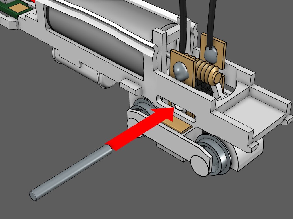
Step 13
1 .Push the pin through the frame, through the truck, and through the gear until it sits evenly across the frame.
2. Make sure the truck can freely rotate without any resistance. If it is stiff, push the pin out and pry open the frame slightly with a screw driver. Double check solder on the pickups is not jamming the truck. If so, sand down the excess solder.

Step 14
Make a half loop with the wires coming from the powered truck. Bend them back toward the rear of the frame them loop them back toward the front. This will provide slack to allow the powered truck to rotate freely.

Step 15 A
Pull the wires toward the circuit board and position the ends over the nearest open terminals.
Do not cross the wires.

Step 15 B
Solder the left hand wire to the left hand terminal.
Step 15 C
Solder the right hand wire to the right hand terminal.

Step 16
Place the dummy truck onto the frame then insert the screw.
Test Running The Frame

Give it a go!
With all the components applied to the chassis, it’s time to test it out on the tracks.
For best results, use a PWM throttle that puts out 6 to 9 volts max. Good examples are Medvend throttles and the Snail Speed Controller sold at Ztrack Center.
NOTE: The frame will run better with the shell mounted because of it’s weight.
Assembling the Shell
Plan Ahead
The handrails, pilots and grab irons may get in the way of painting and adding decals. If any decals will cover an area that has grab irons, it will be better to attach the grab irons after applying paint and decals.
Drill & Tap the Coupler Holes
To install Micro Trains body mounted couplers, the holes under the front and rear pilots will need to be drilled and tapped.
Use the Micro Trains tap and drill set (MTL 1059) to prep the holes.

Clear The Mounting Holes
There are thirty-two mounting holes for grab irons and handrails all around the shell. The 3D print is designed with over sized holes to make up for inaccuracies during the metal casting process. Even so, some of the holes may be clogged up.
For best results, use a #76 drill bit to clear the holes.
NOTE: Smaller drill bits such as #80 are too fragile to clear the holes. They are likely to break.

Already Have Grab Irons?
If you purchased the shell that comes with grab irons, there are only four holes to clear out. All four are in the rear cab area.
Skip to Step 8 when complete.
Step 1
On the far right of the hand rail set there are three grab irons that are different from the rest. They have three points that mount into the shell.
Cut two of them from the handrail set.
NOTE: There is one extra.

Step 2
Find the three holes on the front left of the shell. Insert each of the three points on the grab iron into each hole. Repeat this step for the front right of the shell.
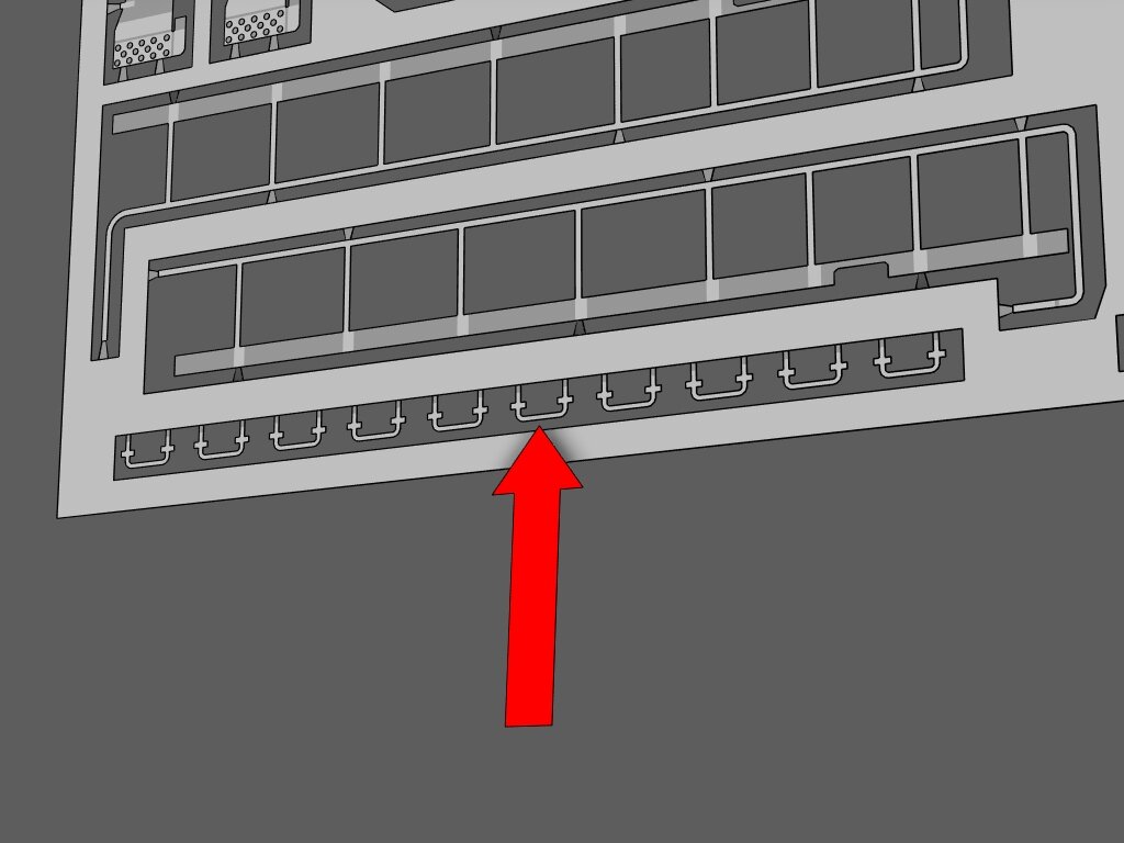
Step 3
Cut out nine of the standard two point grab irons.
NOTE: There are three extra.

Step 4
Attach three of them on the front right of the shell. Attach one above the head light opening.

Step 5
Attach four on the side of the long hood in front of the cab. Attach one on the top of the hood.

Step 6
On the right side of the handrail set there are three long grab irons with two mounting points. Cut out two of them.

Step 7
Attach the long grab irons vertically on the right and left side of the cab door.

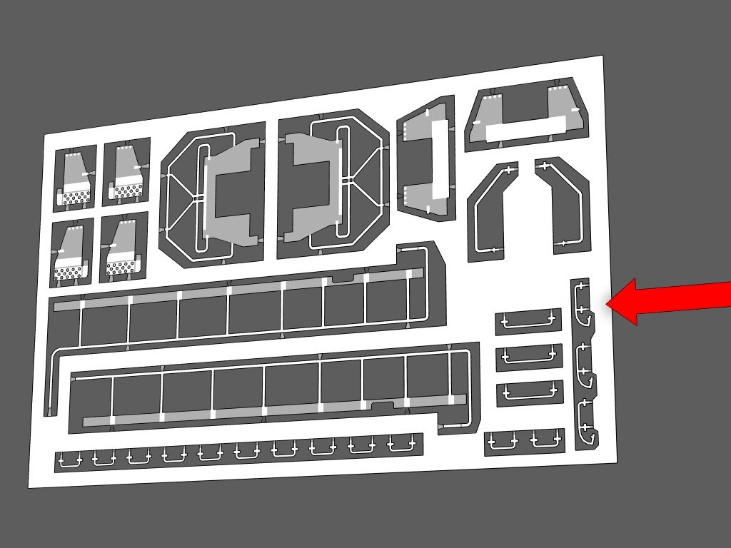
Step 8
On the upper right of the handrail set there are two handrails for the rear stair case. Cut them out.

Step 9
Note the indention on the rail near the mounting point at top and bottom. This is where the rail will be bent so it can be attached to the shell.

Step 10
The indention is where the points will be bent 90 degrees. The illustration shows the handrails in the orientation that they will be mounted to the shell. Notice how all points are bent toward the same direction while the handrails are oriented in opposing positions.
Bend the points 90 degrees as seen in the illustration.

Step 11
Attach the handrails to both sides of the rear cab.

Step 12
Cut out the left side handrails.
Step 13
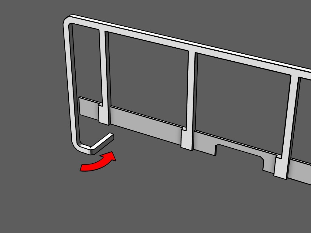
On the part of the rail that drops down, there is an indention where you will bend the rail.
With the etched details facing you, bend the segment 90 degrees away from you (this segment of the rail should go under the walkway).

Step 14
The left side handrail section curves upward so it can connect to the cab area. The top part of the rail must be bent 90 degrees so it can fit under the hood of the cab. There is no marker on the handrail set.
Measure .75mm (.03 inches) from the end and bend it 90 degrees. An optional step is to simply cut it off.

Step 15
Attach the left side handrails to the shell.
NOTE: There is a notch on the handrail that lines up with the details on the shell. The red arrow in the illustration shows where the notch is.

Step 16
Cut the right side handrails free and repeat step 13 before attaching it to the shell.

Step 17
Cut out the two pilot handrails.

Step 18
Bend back the two small flaps on the bottom of the pilot. Notice the etched details are on the front of the pilot. The flaps must be bent in the opposite direction as the details.

Step 19
Attach the pilots to the front and rear of the shell. The two small flaps at the bottom of the pilot should lay flat against the bottom of the stair cases.

Which Pilot Style?
Check photo references of the the prototype you are modeling to determine which style of pilot to attach to the shell.
Open Pilot

Step 1
Cut out the four panels in the top left corner of the handrail set.

Step 2
For all four pieces;
A. Fold the step 90 degrees.
B. Fold the small flap up 90 degrees.

Step 3
With the steps facing outward, attach two of the panels to the front and two to the rear of the shell.

Closed Pilot

Step 1
The closed pilot panels are on the top right of the hand rail set. Cut them both out.

Step 2
With the etched details facing outward, attached the panels to the shell.

Assembling Truck Details

Clean and Prep
Wash the plastic truck details with alcohol and/or Dial dish detergent and warm water. Gently scrub every surface with a toothbrush. Let it dry.
Apply a coat of plastic compatible primer. Don’t prime or paint the back side (smooth side).
Paint in desired colors.
NOTE: Tamiya primer for plastic is recommended.

Step 1
Gently snap off each detail part from the sprue.
Take note of the flange on the backside of the details (see the illustration). The flange will sit flat against the bottom of the shorty truck.

Step 2
Test fit each part before applying glue. Be sure the back of the detail parts sit flat against the side of shorty truck.

Step 3
Glue the detail parts onto the shorty trucks.

Last Step
Push the shell onto the frame. The circuit board is at the front of the locomotive.
